
Rey.BEng 5th September 2026
Intro
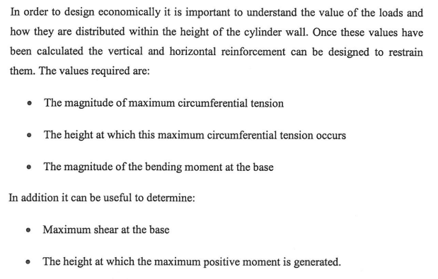
In 2008 the design question was already narrow. An elevated cylindrical tank must give three numbers before any bar is scheduled: the maximum circumferential tension, the height at which it occurs, and the restraint moment at the wall–base joint. Shear at the base and the height of the maximum positive moment are useful extras. Those five values are what the PCA coefficients, and every handbook method compared in the thesis, are for.
The wall is a thin cylindrical shell. If the base can slide, the hoop force follows the water pressure and is largest at the bottom. If the base is pinned or fixed, part of that force is taken as vertical bending. The water load does not change; it is partitioned. Figure 1.3.4 of the thesis is still the picture.
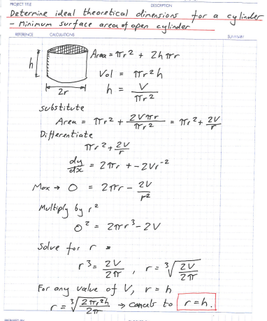
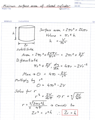
Appendix I is unchanged. For a fixed volume the least surface area of an open cylinder is at r = h. For a closed cylinder it is at 2r = h. That is only a starting size. Cost of concrete, steel, formwork and the tower will move the dimensions.
The 2008 method then read coefficients K1, K2, K3 from the PCA tables. The Excel sheets in Appendices II–V did that job. They remain the control cases. This project repeats those same tanks. The classical partition is kept. An extra hoop term sigma_R is added only after the PCA values are on the page. When the extra term is set to zero the 2008 output must reappear.
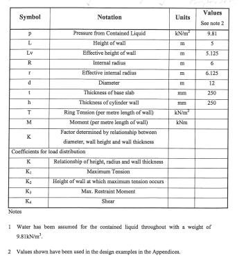
Notation stays with the thesis: L height of wall, R internal radius, h wall thickness, T ring tension, M moment, K and K1–K4 as in Batty and Westbrook / PCA.
1. What the 2008 thesis asked for
The three design values, plus shear and the height of maximum positive moment.
2. Notation (do not change)
3. The partition of the water load
Unrestrained wall: hoop follows the pressure triangle.
Restrained base: some of the same load becomes cantilever bending. Tension at the base falls toward zero.
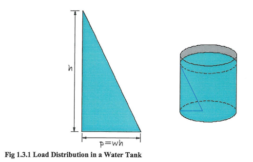
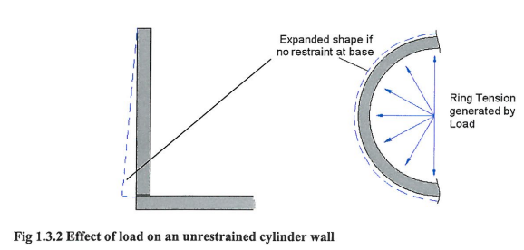
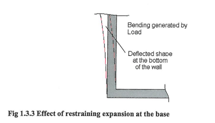
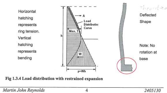
Fig 1.3.4 is the graph the sliders must still draw.
4. Joint at the wall–base
Sliding, hinged, or continuous. The 2008 examples assume the top free and the base prevented from rotating except as the chosen joint allows.
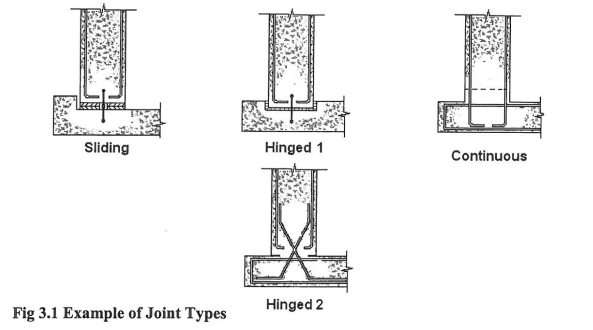
5. Appendix I — starting size, unchanged
Minimum surface area for a given volume:
- open cylinder: r = h
- closed cylinder: 2r = h
No ring-tension term is required for this proof.
6. The 2008 further-study list this page answers
Tasks 1–4 of §6.1: provenance of the PCA tables, translation of Lewe, follow-up of references, and a method from one shell theory. This page is the worked-example half of task 4. Tasks 5 and 6 (base-slab deflection, prestress) stay closed for now.
[insert screenshot: thesis pages 46–47 — §6.1 items 1 to 4]
7. Next on this page
Appendix II of the thesis: the same tank calculated by the handbook methods. That set becomes the PCA control column. Then the same numbers again with sigma_R, and the slider page with three knobs: L/R (or the PCA K argument), wall thickness h, and k_R with k_R = 0 forced to recover the 2008 graph.
Screenshot list (in order)
- p.2 Abstract bullets
- p.4 Notation
- p.9 Figs 1.3.1–1.3.2
- p.10 Figs 1.3.3–1.3.4
- p.27 Fig 3.1
- p.49 Appendix I cover
- p.50 open-cylinder calc
- p.51 closed-cylinder calc
- p.46–47 §6.1 tasks 1–4
When those nine are on the page, send Appendix II and we set the control table.

