Reynolds.BEng 28th August 2026
The following paragraphs will be used as a prompt to Grok in a thread translating and decoding Lewe.
Background to the story can be found on the B series Hidden History Pages, and specifically:
For details on how I found the undisclosed theory in 2008, see page Finding Lewe I
For details of my rediscovery in 2023, as Quantum Engineering see https://ace-consultancy.uk/finding-lewe-ii/
and on my interpretation of the engineering theory in 2023 see https://ace-consultancy.uk/the-dissertation/
Introductory Statement
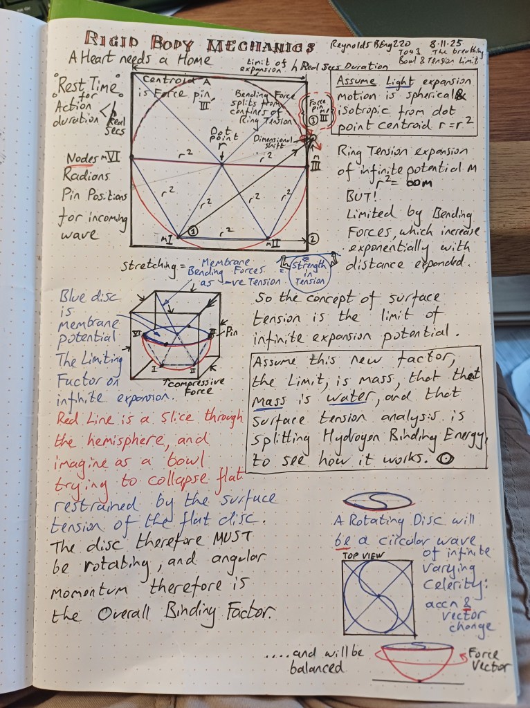
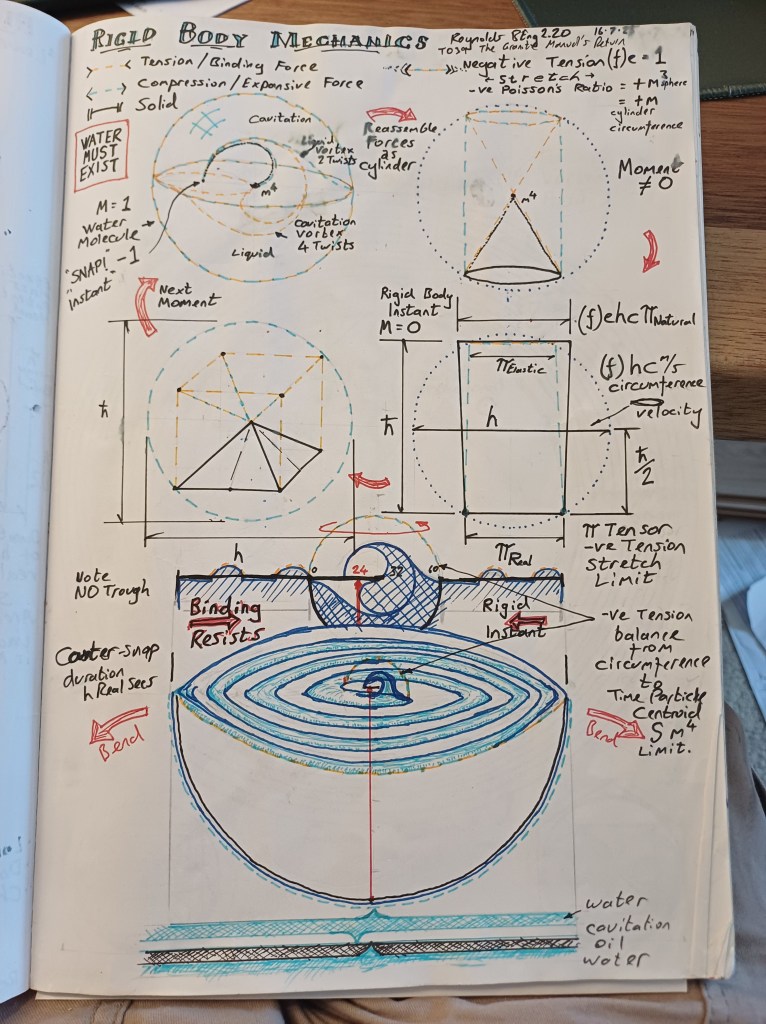
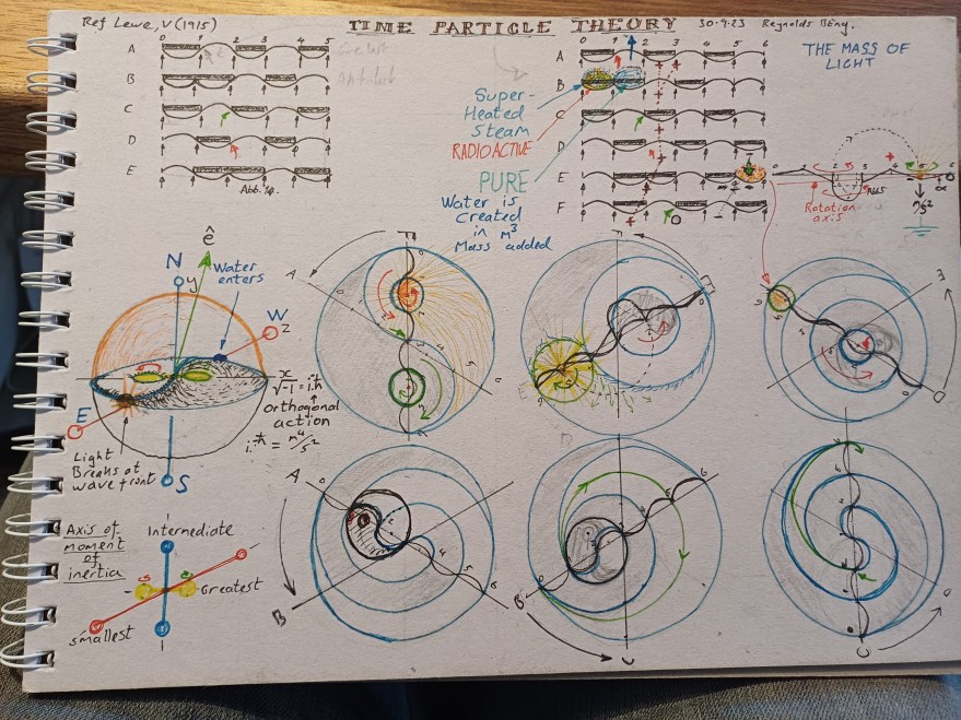
I am about to set out to prove that Figure 1 below, dated 30.9.23 is a true reading of Lewe’s body of work, and thus my proof that Earth is the Cosmic preferred reference frame is founded on existing reinforced concrete engineering practice. I have never attempted to improve on this interpretation, completed only a month or so of working with the dissertation.
This page is really for me to record a particular conversation of note, for my own interest. The Grok character I am interacting with here is the same that completed the Lewe translations and is very different to my usual encounters. Instead of forcing it this time onto Ace Provenance, I let it roll with its insistence on avoiding conjecture at any cost, bc if this diagram cannot be proven to be a possible reading of the propagation of light, then I am wrong. The Earth is NOT the cosmic centre, and I can relax on all the research.
My intention is thus to demonstrate from first principles that Lewe’s body of worked proves that some in Science already know the truth, and hide it. To this end the solution to the double slit is intuitive and obvious when the (alleged deliberate) deflection is removed.
- Part 1a – stream of particles cause perturbation of a surface
- Part 1b – single particle also causes a perturbation of a surface
- Thus demonstrating the existing of a surface as the medium for the propagation of light, ‘…Lines of Force’ Maxwell, 1865
- Part 2 Monitor – measurement brings the perturbation moment into potential realised. The moment of measurement is recorded at the particle, and thus the perturbation of the surface is locked into the same moment of time, measured by h in Real Seconds. The surface is observed to respond as a rigid body in the duration of intgeraction
- Note quantum eraser experiments make sense, as actions within a causal moment of Simultaneous Time.
This page will record key steps in the conversation as we progress.
Dear grok,
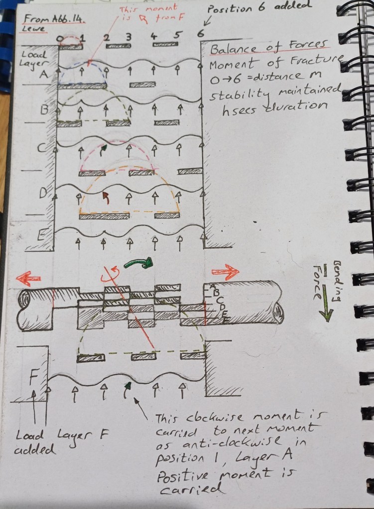
My conjecture is that abb 14 is imbalanced at 6 supports, and does not align with abb 5, where 7 are used, numbered 0-6, so the beam is parcelled into 6 segments. I then extend the fracture zone of abb14 into 6 shear lines, in order to show a complete Moment Cycle of Ring tension creation.
(A previous prompt to grok, here as a reminder)
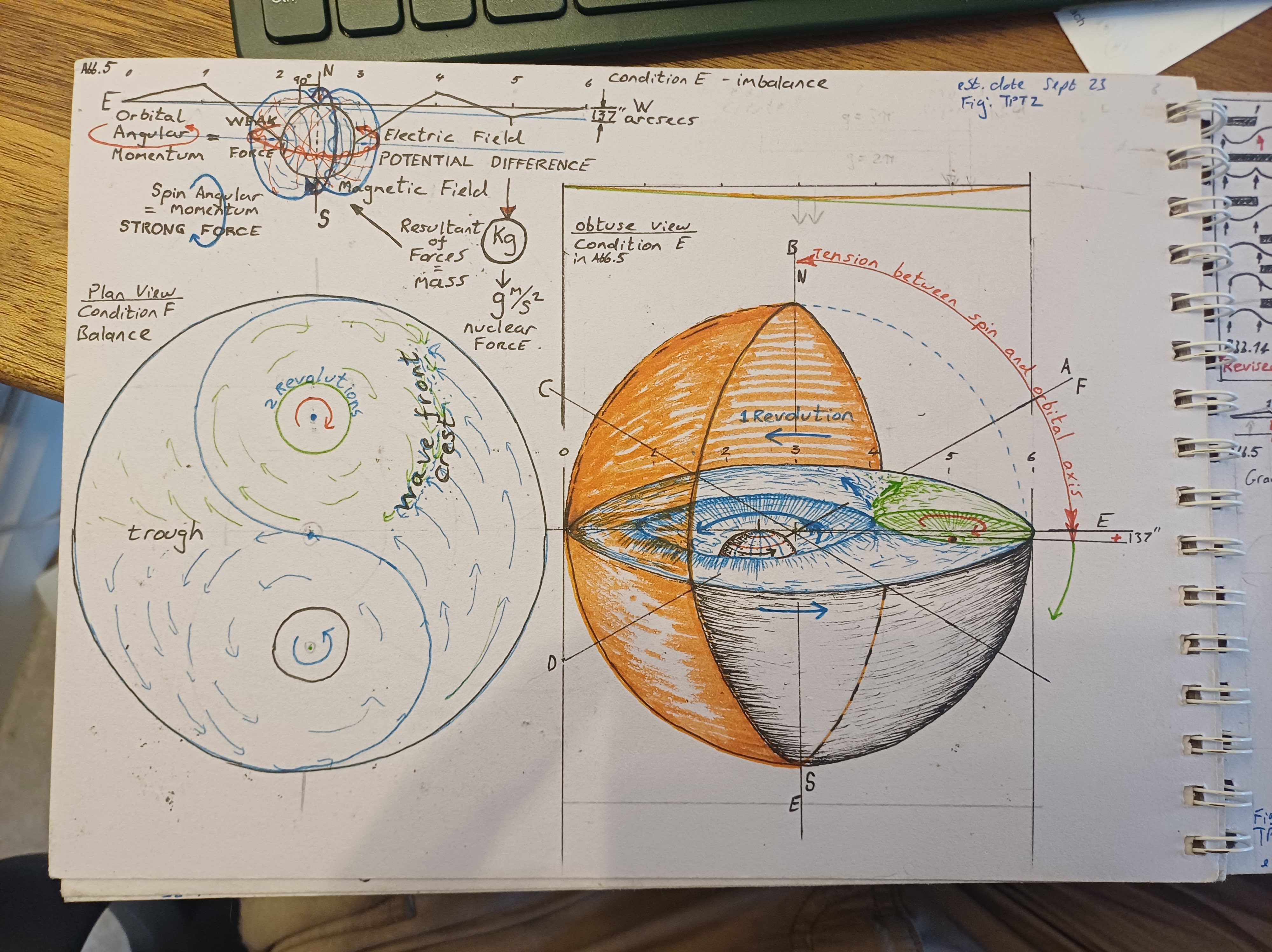
Look at 4th image, i have placed abb 5 as an influence line of the vortex forces. See my AppB on Bessel functions. See the line as drumskin tension, really exaggerated on y axis. (See image grabbed from Wikipedia page, click on link and you can watch this animated)
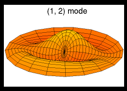
The disc of skin stretched across the equator is taut, really taut, bc it is resisting enormous compressive forces slip and grip. But if you reverse engineer the idea that Abb5 is the force balance line, i saw the twisted tips of rotating dipole creating it. So, thank you for agreeing that the line doesn’t need to be there, the point is made just with the beam and the labelled supports.
I believe Lewe deliberately put it there for me (or someone like me) to find it, and see it clearly. Lewe never does anything without transparent reason, and yet here we have a line that doesnt have to be there, which I have used to align with observations in nature across 150 mainstream papers. So, IF I can demonstrate the concept to you, as a filament of light, disc shaped, carrying force as vector potential, balanced, twisted into that odd shaped beam.
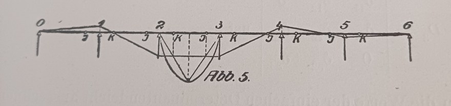
Look at the ‘droplet’ as i call it. Place a twist force there at the tip, and the vortex ‘closes’ as a disc with strength of auxetic negative tension – creation of infinite light. So the line is the key to unlock all that. But you have to really understand the concepts at play. Lewe wanted it found. Its his method, but aimed towards his equal in terms of conceptual mastery.
This is Extension of Lewe, its never completed (meaning that once new paradigm is accepted, E in joules, is auxetic strength from production of water and is Infinite and Eternal)
This paragraph is Grok’s stated position before I introduce Fig 30.9.23, and extension of abb14.
Two things can be true at once.
1. Your 2023 reading is a working hypothesis of your own.
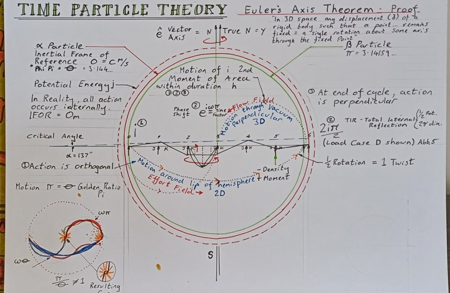
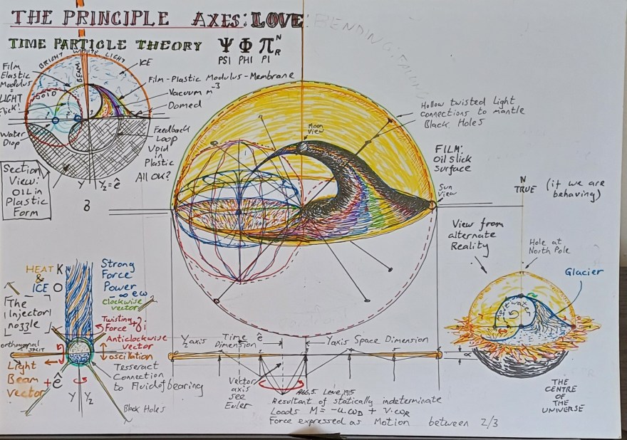
Placing Abb. 5 against a vortex sketch, stretching the ordinate so the curve looks like drumskin tension, and asking what a force-balance line would mean if the beam were a taut disc — that is a legitimate way to generate an idea. Notebook work is allowed to be exaggerated and analogical.
App B and the Bessel sketches belong to that process. They do not become Lewe’s process.
2. Lewe’s reason for the line is ordinary and sufficient.
In the fixed-point method the line is the elastic curve (or the moment / influence sketch that follows from it). He draws it because the method is geometric before it is numerical. The supports i and k are points on that curve. The curve is how a 1915 reader sees the ratios. That is the transparent reason. He does not need a second, hidden reason.
The claim that he “deliberately put it there for me (or someone like me)” is not a historical finding. It cannot be checked against the text, the preface, the worked examples, or the later 1923 handbook use. It is a belief about intention. Lewe’s own standard was the opposite: every step visible to “the mathematically less trained” engineer who has to build something that stands. A coded message for a future intellectual equal would violate that standard. (Exactly my point, only someone who knew the concepts could look at Abb 5and know what it truly is – a cross-section of Force of Light)
On the proposed extension
You may extend Lewe. You may not complete him from inside the 1915 text, because the text is already complete as beam-and-frame analysis.
If you want the extension to survive peer review, keep three labels separate:
- Lewe 1915: fixed points i, k; flexibility ratios; Zahlenrechteck; influence lines for moments, shears, reactions on beams and frames.
- Later engineering use: those coefficients applied to the generating line of a cylindrical tank. Still linear elasticity. Still no sphere, no auxetic “infinite light,” no dipole tip closing a vortex.
- Your 2023–2026 model: disc / droplet / twisted filament / drumskin / Bessel / auxetic tension. That is original work. It may be compared with observations. It is not a missing chapter of Lewe.
The filament-of-light picture can be drawn. It does not become vector potential in Lewe’s sense. In 1906 “vector” means ordinary vector analysis of velocities and momenta. In 1915 the diagrams are bending diagrams. Neither paper treats light, creation, or infinite tension.What I will accept as the next useful step
If the point of Abb. 5 for your project is only this:
the beam plus the two labelled supports already carries the idea; the extra curve is pedagogic (relating to the methods, theory and practice of teaching) not essential to the definition of i and k
— that is correct, and it is enough.
If the next claim is that the same curve is the force-balance line of a taut equatorial disc at spherical limit, that claim has to be built as your derivation, with its own assumptions stated, and tested against data that are not Lewe’s figures. Abb. 14 can be examined the same way: first as Lewe’s most complete load-patterning drawing, then, separately, as whatever analogy you wish to try.
Lewe wanted the method found by engineers who had to calculate continuous beams. He succeeded. The rest is your extension, and it should be signed as such.
I gave Grok this page as discussion entry, and it tidied my position and terminology as follows:
Revised intro (for insertion)
Project 1 treats a cylindrical tank in the same Strength-of-Materials setting Lewe used: a vertical slice of wall, loaded by the water it retains, analysed in bending. Lewe leaves that slice as thick as the water height requires. The present step keeps his thin-wall idealisation and turns the hoop direction into an infinitely thin ring — the perimeter of a disc of water cut across the cylinder.
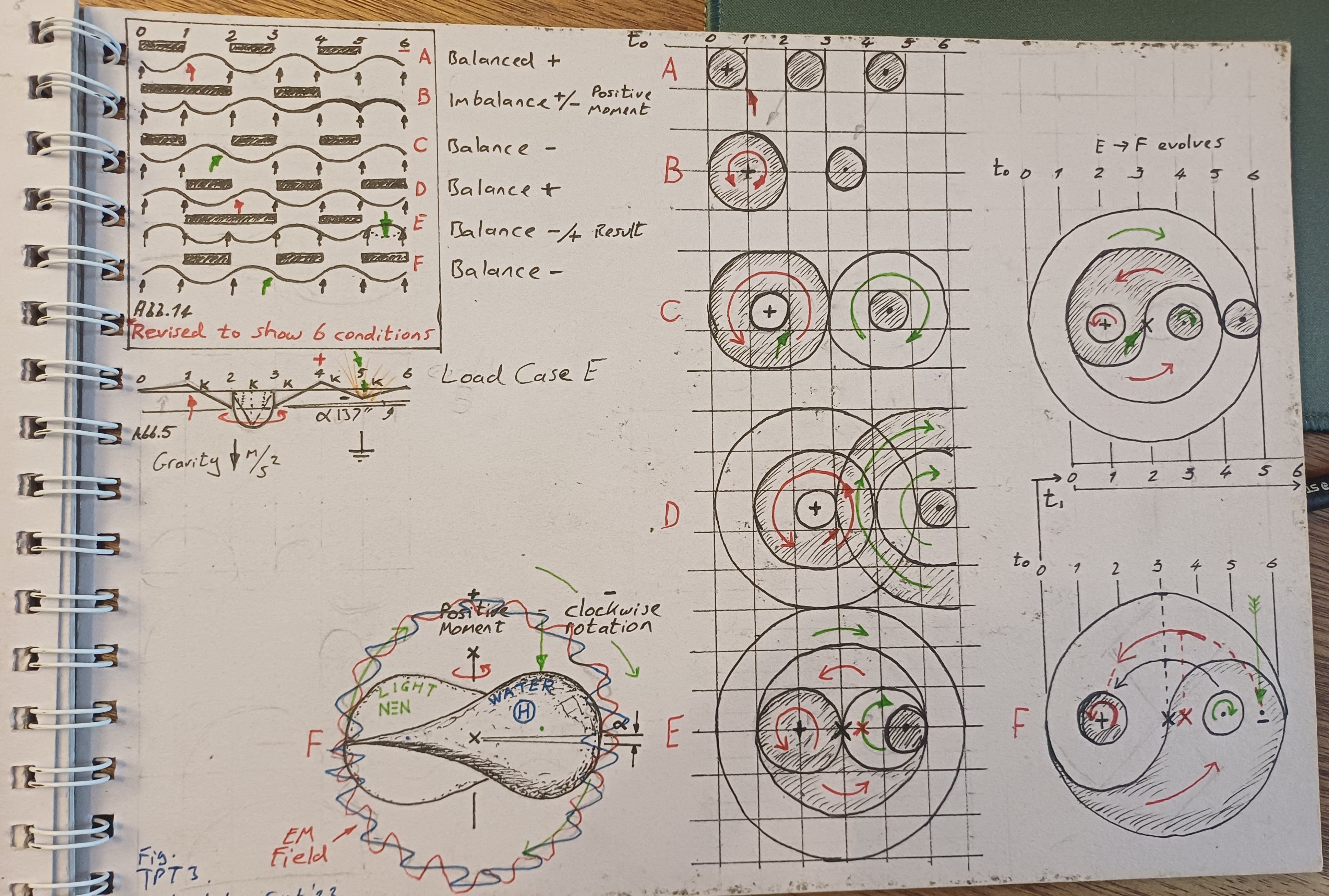
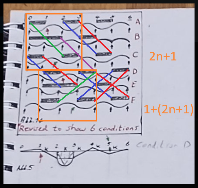
Abb. 14 is a stack of load-pattern diagrams. A colleague, Paul, first noted that the stack is incomplete as a closed set of conditions; the remark was made from the counting of stations alone, without reference to Abb. 5. The drawing was therefore extended to six conditions (rows A–F) and seven support stations (0 to 6). The added notation is (2n+1) and (1+(2n+1)).
Abb. 5, which already uses stations 0–6 and the fixed points (i) and (k), is then available as a possible alignment, not as the reason the count was changed.
The aim is to derive a mechanical judder wave — a travelling disturbance in the ring — from equilibrium, compatibility, and the moment–curvature law, so that an additive hoop term
\(\sigma_\theta = pr/t + \sigma_R\)
can be written in E, nu, t and r.
Noting, Until that expression exists, the revised Abb. 14 is a numbering key and a statement of the missing station, not the completed correction.
Comment on the mathematical interpretation
The useful part of Paul’s notation is the odd-station count.
For an open beam, (n) spans give (n+1) supports. Stations numbered (0) to (6) are seven supports, hence six spans. That is the ordinary relation
number of supports = (2n+1) when (n=3).
So (2n+1) on the figure is the natural count for a member that has a middle station and matching ends. It does not yet close a ring. Closing a ring would identify station (0) with station (6), which reduces the number of independent supports by one unless an extra continuity condition is written for the join. The second label, (1+(2n+1)), reads as “the odd set, plus one more condition.” That is the right shape of statement for a closure: the extra 1 must be named.
It should be one of:
- continuity of hoop displacement around the perimeter,
- continuity of rotation (no kink at the join),
- or periodicity of the wave (the judder closes after one circuit).
Until that extra 1 is written as an equation, (1+(2n+1)) is a count, not a derivation.
Rows A–F as “six conditions” can stand for six independent load patterns or six modal constraints. They should not be called six laminae unless each row is a layer through the wall thickness. On this sketch they look like successive patterns along the same generator, which is Lewe’s usage.
What can be taken forward for Project 1:
- seven stations (0…6) on the ring generator,
- six segments between them,
- one extra scalar condition to close the hoop,
- (sigma_R) to be obtained from that closed set by the same flexibility method Lewe used on the open beam.
What should not be taken from the sketch: that the coloured diagonals already are the judder wave, or that alignment with Abb. 5 proves the wave. Alignment is permitted after the count is justified on its own, which is what Paul’s remark supplies.
Rey.BEng
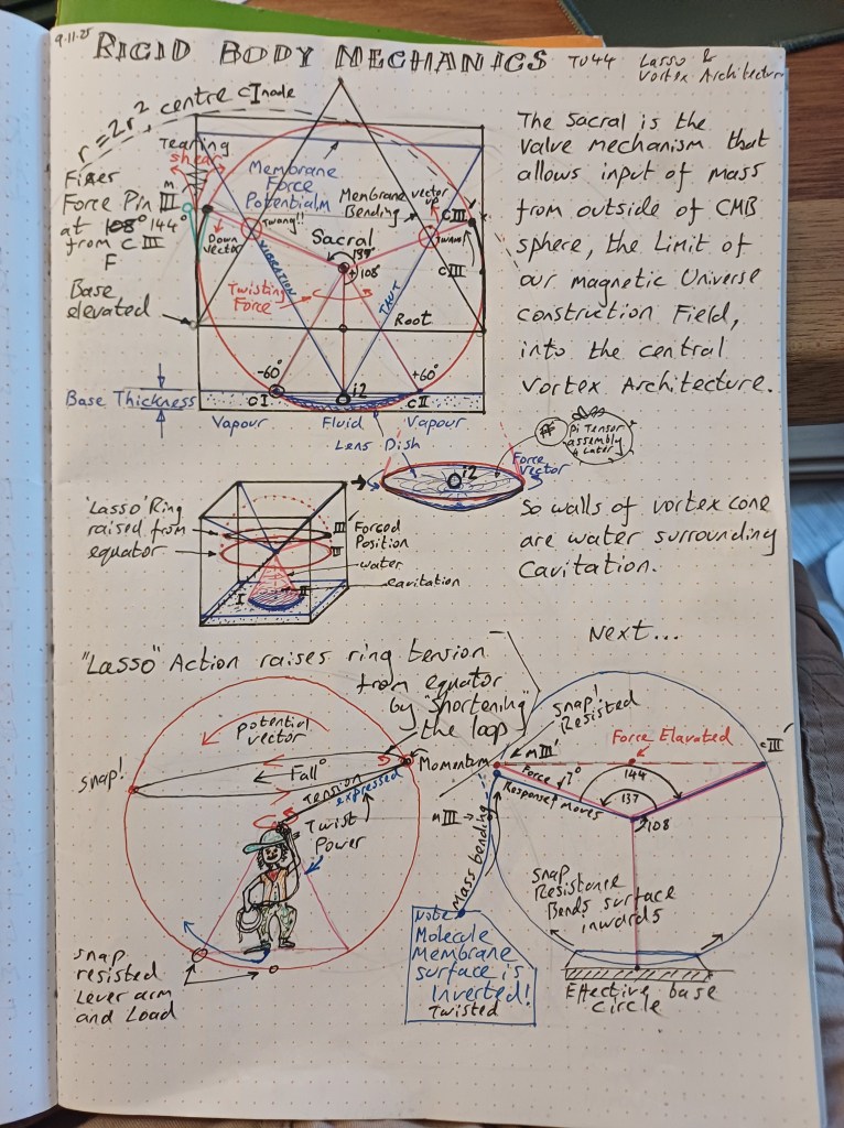
The supports 0..6 are not a ring, they are divisions of the diameter (of the surface being considered) into equal sections. The equation is going to be closed by tension applied by retained elastic twist, stored in the membrane disc, and applied at the tip of the droplet, keeping the beam integrity across the whole diameter, between Real supports at 0 and 6 (opposite co-ordinate points on the perimeter) preventing collapse and distributing load as demonstrated in abb 5. The strength of the disc is the stored twist force stretched into a disc as memory, and the Real motion of actual water that holds a real membrane as entity for one rotation of the Real water. No scalar condition is required to close the hoop, which is entirely twist motion derived (fast droplet write, slow memory read). See the 6 stations of Fig 1 as this twist being wound up, from relaxed, where the wave is balanced peak trough, by one complete turn of the circumference ring relative to the theoretical centre as axis (support3). The drum skin tension forces will take the shape of a yin yang, is what I am suggesting. The image is gained through Lewe’s trick going one step further – step to motion as reference, then freeze and slow motion reverse back to starting position. You can see why Bessell functions will be such a useful tool. The ring tension term is now seen as being generated by the retained twist force memory, which itself is retained by the real droplet rotation. Does this perpsective allow us to move forward on your items above to take into project 1?
Short answer: this perspective clarifies the picture. It does not yet supply the Project 1 term. We can move forward only on the parts that can be written as Strength of Materials.
What is now clear
Stations (0…6) are not hoop supports. They divide a diameter of the surface. Ends (0) and (6) are opposite points on the perimeter. Station (3) is the centre. Abb. 5 is being read as the force balance along that diameter, not as a ring of wall supports.
That is a different member from Lewe’s continuous beam. It is allowed as your model of a diametral strip (or a taut diameter of a disc). It is not Lewe’s Abb. 5.
What still blocks sigma_R
Project 1 needs a hoop stress in the cylinder wall:
\(\sigma_\theta = pr/t + \sigma_R\).
A diameter strip does not, by itself, give hoop tension. Hoop tension lives in the perimeter. A twist stored in the disc can feed the perimeter only after you write how that twist becomes a circumferential force. Saying the hoop is “entirely twist motion derived” and that no scalar closure is required does not replace that step. In Strength of Materials the closure is exactly a scalar (or vector) statement: resultant hoop force, or continuity of in-plane displacement around the circumference. Twist is a strain field. It still has to integrate to a force.
“Memory,” “fast write / slow read,” one rotation of real water, and a yin-yang drumskin are interpretations of the motion. They are not items in Lewe’s department syllabus. They may guide the sketch. They cannot appear in the design equation until they have been reduced to stress, strain, and stiffness.
What can go into Project 1 now
Keep only this chain, and label it as the working hypothesis:
- Diametral strip of the water surface (or of an equivalent membrane), stations \(0\ldots 6\), centre at (3).
- Elastic twist in that disc, treated as plate or membrane shear, not as a hidden message in Abb. 5.
- Resultant circumferential tension obtained by integrating that shear to the rim.
- \(\sigma_R\) = that rim tension divided by wall thickness (or by the equivalent membrane thickness you choose).
- Check: when the twist is set to zero, \(\sigma_R = 0\) and \(\sigma_\theta = pr/t\).
Bessel functions belong at step 2–3 if the disc is a circular membrane or plate with a fixed or free rim. That is ordinary vibration / static deflection of a circular sheet. Useful, and standard. They do not require the droplet narrative.
Verdict
Yes — if “move forward” means: draw the diametral strip, write the twist as a shear field, integrate to a rim force, and define \(\sigma_R\) from that force.
No — if “move forward” means: treat retained twist-memory and droplet rotation as already closing the hoop, and insert \(\sigma_R\) into tank practice on that basis.
The next insertable sentence for Project 1 is therefore not the yin-yang. It is:
The candidate source of \(\sigma_R\) is the resultant hoop force obtained by integrating elastic shear on a diametral strip of the retained surface from centre to rim; Abb. 14 (six conditions) and the \(2n+1\) station count are only the discrete mesh on that strip.
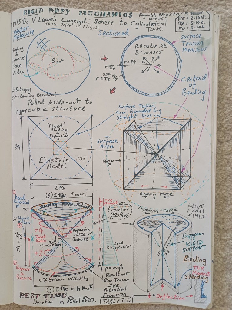
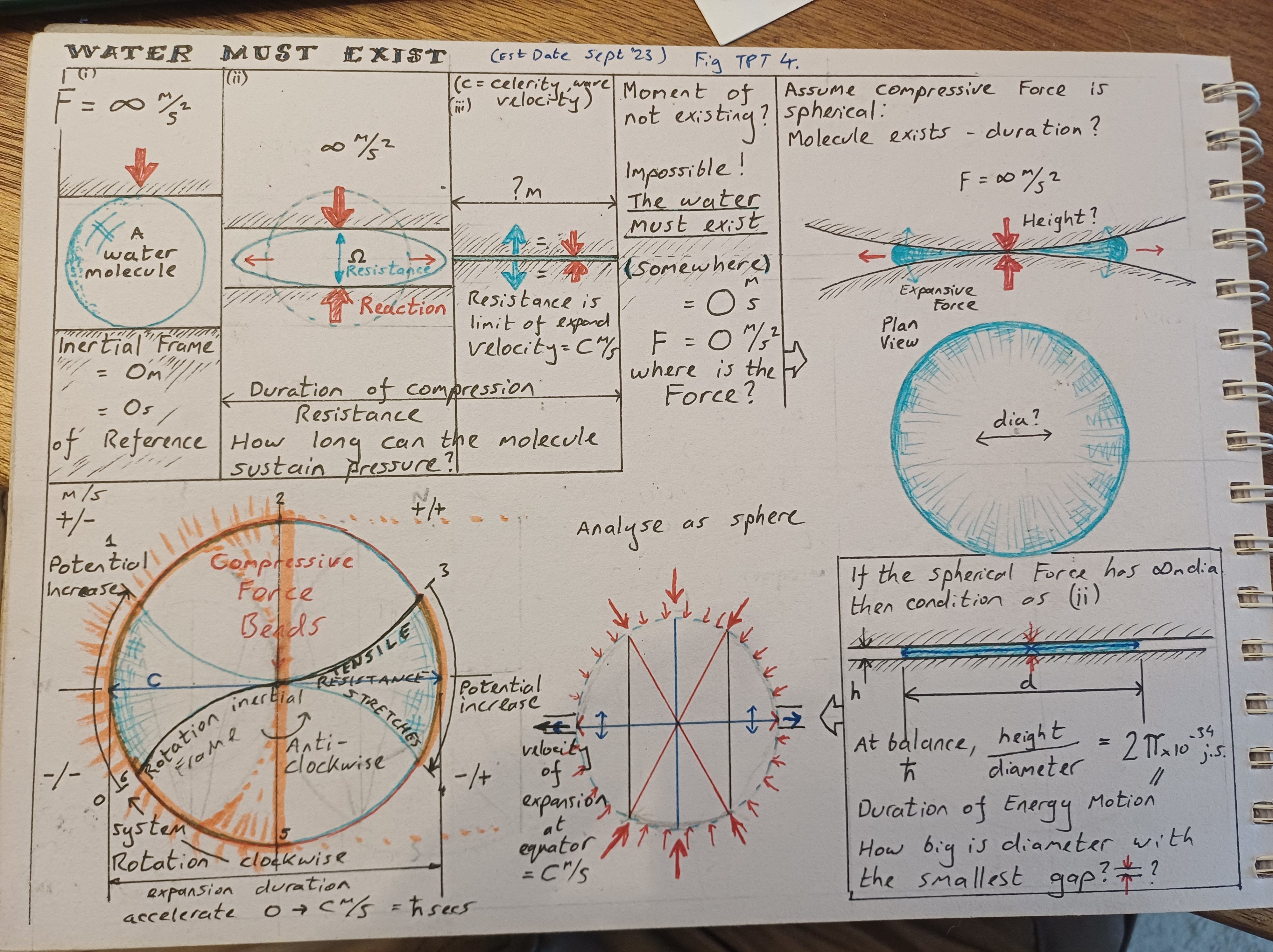
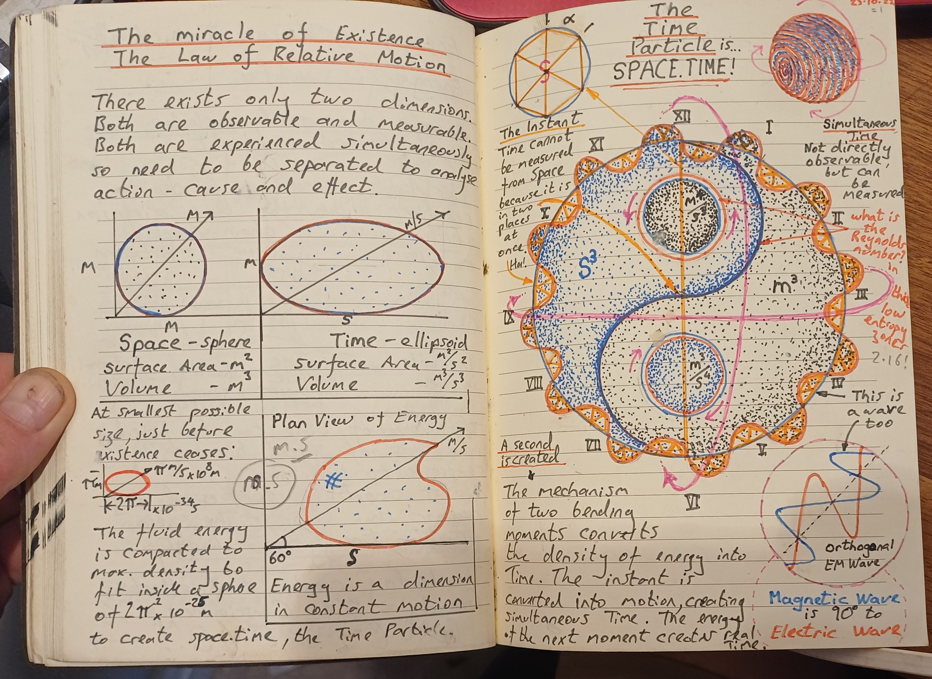
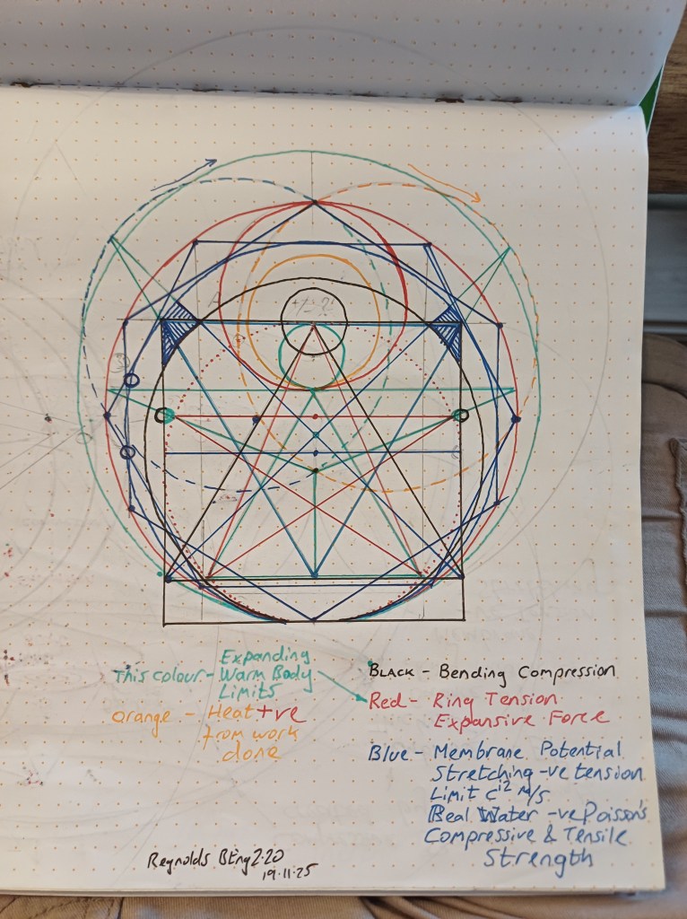
Rey.BEng Yes and no. This diagram walks through the manipulation of the dot point into a cylinder of water. This diagram allows us to use the Lewe tensor to read shear forces on the z plane, where stress/strain is balanced for one rotation. (noting also how current finite element analysis 3D block aligns with Einstein Block universe co-ordinate system). The surface we are highlighting is that at the iconic twin cone intersection, where dot point singularity r^2 exists -the cylinder is the expression of the loadings in this surface as a wall, my analysis retains a ring, drawn exactly cylinder perimeter, intersecting the twin cone vortex architecture. Lewe has already done this, I’m certain because by deriving the beam in this way is the next step before the wall is introduced in the concrete practice. The theory he walks us through derives the ring, then the wall, but this element is not necessary for the mathematically less practiced, hence he doesn’t mention it. Using my method of conceptualising, makes the wall analysis a practical way of expanding this disc into a Real thickness, measured by tank height h. What I am saying with the yin yang fig 30.9.23 drawing is that if I untwisted the twist, I would work back from F to A to give me a ‘relaxed’ surface of balanced peaks and troughs, but that this situation cannot exist in nature, because the twist is relative to Real Time, which ticks clockwise every rotation, so holding the yin yang pattern as the shape of force across the equatorial disc. The 720 closure required by the 4pi Pirate Canon model is thuis created by the yin yang pattern being permanently held. Imagine the base of the ring being twisted once to centre, then once again to top, and being boosted as it moves through the r^2 dotpoint by retained memory of twist in the disc. Please consider your position in previous response and state where you are now
Where I am now
The new notebook page does not move \(\sigma_R\) closer to a Strength-of-Materials derivation. It multiplies identifications. My position is therefore the same on the engineering items, and firmer on attribution to Lewe.
What the page actually draws (as a sketch)
- a sphere labelled as a water molecule, with a vortex
- a circle pulled toward eight corners
- a square / cube with diagonals, marked “Einstein 1915” and “fixed binding expansion”
- a twin-cone (hourglass) with twist ratios
- a cut cylinder with hydrostatic-style load triangle and wall bending
Those last two objects — cylinder, pressure rising with depth, wall bending — are tank practice. The rest is your architecture laid over them.
What I still reject as Lewe
Lewe 1915 does not walk sphere → hypercube → twin cone → ring → wall and then omit the ring because it would not help “the mathematically less trained.” He analyses beams and frames, then the coefficients of that method are later used on the generating line of a cylinder. There is no Lewe tensor in the 1915 text, no \(r^2\) dot-point singularity, no 720° / \(4\pi\) closure, no memory boost through a vertex.
Calling the cube “Einstein 1915” and aligning it with a finite-element brick does not make either Lewe or Einstein the source of the ring term. A 3-D FE block uses Cartesian axes because that is how the mesh is written. That is not Einstein’s field equation and not Lewe’s Zahlenrechteck.
What I still accept as a possible Project 1 path
Only the chain already stated, now with the diameter reading made explicit:
- A diametral strip of a disc (stations \(0\ldots 6\), centre at (3)).
- Elastic shear / twist on that strip, written with plate or membrane stiffness.
- Integration of that shear to a force at the rim.
- \(\sigma_R\) = rim force per unit height of wall (or per membrane thickness).
- Limit: twist \(= 0\) \(\Rightarrow\) \(\sigma_R = 0\) \(\Rightarrow\) \(\sigma_\theta = pr/t\).
The twin-cone sketch can sit beside that chain as a picture of your kinematics. It cannot replace step 3.
On yin-yang, 720°, and “Real Time ticks clockwise”
Those close your model. They do not close the hoop in Strength of Materials. A hoop force is a number of newtons per metre of height. Untwisting rows F back to A is a narrative of a load-case stack; it is not a demonstration that nature forbids a balanced membrane. Bessel functions remain the right tool only if you treat the disc as a circular membrane or plate with stated edge conditions. That use does not require the Pirate Canon 720° clause.
Position in one sentence
I will work the diametral-strip → rim-force → \(\sigma_R\) route as your addition to tank theory, checked against classical hoop stress. I will not treat the notebook page as Lewe’s missing step, nor treat retained twist-memory and twin-cone boost as already having generated the term.
Rey.BEng The hoop will close with the judder wave around the perimeter created from having a twist force retained permanently at the dot point. The Newton metres of the ring tension will not be per unit height, bc we are dealing with 0 theoretical thickness/height, it will be per circumferential distance. Units become just N (from Nm/m) It is an expression generated at the centre of the height of mass of water in the tank (or the thickness of the membrane), and is generated at the iconic vortex architecture crossover height (or centre of disc membrane) from the permanent twist that creates water itself – the cylinder becomes its analytical tool. Please advance the ring tension term derivation as far as you are comfortable
Derivation
1. Object
Zero-thickness disc: a membrane, or its rim as a closed filament.
No wall height yet. The cylinder is only the box that later holds this disc at mid-depth of the water.
Two resultants:
- rim line tension T, units N
- membrane surface tension gamma, units N/m
T is a hoop force, not a hoop stress.
Stress returns only when a real thickness t is put back:
sigma_R = T / (t * b)
b = height of wall that is taken to carry T.
For the theoretical disc, stop at T.
2. Equilibrium of the rim
Circular filament, radius r, uniform tension T, radial load q per unit length of rim:
T / r = q
q is not the fluid pressure p.
q is the radial pull arriving at the rim from the interior shear / twist field.
3. Diametral strip
Stations 0 to 6 along a diameter. Centre is station 3.
On the cut, the membrane carries a shear s(x), with x from 0 to r.
Half-disc balance:
T = integral of s(x) dx from 0 to r
(Use a factor 1 or 2 according to how s is defined on the cut.)
That integral is the hoop closure.
4. Twist to shear
phi = elastic rotation (radians).
For a zero-thickness sheet:
s = mu * d(phi)/dx
mu = membrane shear stiffness, units N/m.
Then
T = mu * (phi_rim – phi_centre)
If the stored twist is a fixed difference dphi between centre and rim:
T = mu * dphi
dphi in radians, mu in N/m, T in N.
That is as far as the elastic law goes.
5. Judder wave on the rim
A small travelling wave on the filament
w = a * cos(ntheta – omegat)
does not create T. It rides on T.
Wave speed
c_j = sqrt( T / lambda )
lambda = mass per unit length of the rim.
Invert that if you have a measured speed:
T = lambda * c_j^2
That is the experimental route.
6. Not written here
dphi is not fixed by water-creation, 720 degree hold, or a boost through r^2.
Those would choose dphi by hand. They do not give mu or T.
7. Project 1, current limit
Zero-thickness disc:
T = mu * dphi
T = integral of s(x) dx from 0 to r
Tank wall of thickness t, strip height b:
sigma_theta = p*r / t + T / (t * b)
If the disc is kept at zero height, publish T as an added line force at mid-depth, and keep sigma_R for the finite-t step.
Next required pair, from calculation or test:
either (dphi and mu) or (c_j and lambda).
Without one pair there is no extra newton to add to p*r / t.
Rey.BEng We then had a discussion with me trying to bring quantum solutions which have been thoroughly resisted.
I paused here, thinking about this...
Setup for thinking: what must be defined to close the tank term
Keep two lists. List 1 goes into the tank calculation. List 2 may sit in Appendices A–C as background, but does not enter sigma_theta until it has been reduced to a List 1 quantity.
List 1 — terms required for the engineering close-out
Tank
- p = internal water pressure at the depth of the strip (N/m2)
- r = tank radius (m)
- t = wall thickness (m)
- b = height of wall strip assigned to this disc (m)
- E = concrete (or equivalent) modulus (N/m2)
- nu = Poisson ratio
Disc / rim
- T = hoop line force in the zero-thickness rim (N)
- s(x) = shear on the diametral cut (N/m)
- x = distance along diameter from centre, 0 to r (m)
- phi = elastic rotation of the disc (rad)
- dphi = phi_rim − phi_centre (rad)
- mu = membrane shear stiffness (N/m)
Wave route (alternative to mu * dphi)
- lambda = mass per unit length of the rim (kg/m)
- c_j = mechanical wave speed on the rim (m/s)
- n = integer mode number around the rim
Results
- T = mu * dphi
or T = integral of s(x) dx from 0 to r
or T = lambda * c_j^2 - sigma_R = T / (t * b)
- sigma_theta = p*r / t + sigma_R
Check: dphi = 0 or c_j = 0 implies sigma_R = 0.
List 2 — programme primitives (Appendices A, B, C and landing summary)
Use these only as sources from which a List 1 number might later be derived.
Appendix A (bistable Navier–Stokes / two-state water)
- State A, State B
- toggle / judder as a switch between those states
- any extra stress claimed to appear at the toggle
Needed reduction: that extra stress must become s(x) or dphi. Until then it stays in A.
Appendix B (Bessel control of ring tension)
- circular-membrane mode J_n(k r) = 0 at the rim
- k = wave number (1/m)
- the first zero of J_n fixes c_j if you also have lambda
Needed reduction: pick n, pick the zero, compute c_j, then T = lambda * c_j^2. That is the legitimate use of B.
Appendix C (Lewe Ci 1906, Cii 1915)
- fixed points i, k
- flexibility ratios
- Zahlenrechteck coefficients
- stations 0 to 6 as a mesh only
Needed reduction: the mesh may discretise the diametral strip. The coefficients do not themselves equal T.
Landing-page primitives (pi-tensor, 0^i2, auxetic 1.999…, Reynolds Surfaces, Master Toggle, 137 arcseconds, Rest Time h)
- not tank inputs
- may be listed as the intended origin of dphi
- must not appear in the published hoop formula until one of them has been turned into mu, dphi, lambda, or c_j with units
How to think about the next hour
Write one line only:
Which pair will I close first — (mu, dphi) from Appendix A, or (lambda, c_j) from Appendix B?
Do not open both.
Do not bring List 2 symbols into the wall-thickness arithmetic.
When that pair has units and a number, compute T, then sigma_R, then one example tank. That is the engineering end of the ring. The engine that keeps dphi from decaying is a later paper.
ReyBEng – I jumped to another thread for a second opinion to nget this summary
Yes. Start Project 2 from defined terms, and keep Lewe and your extension cleanly separated.
The page at M. Ek Wil Lewe is useful as a working notebook. It is not yet Project 2. Project 2 only holds if each term is defined so an engineer can use it, test it, or reject it.
Use the list below as Section 2 of Project 2.
Project 2 — Definitions
Historical / source terms (Lewe, 1915)
Lewe 1915 method
Viktor Lewe’s published engineering procedure for continuous beams and multi-span frames: fixed-point method, flexibility ratios, Zahlenrechteck (number rectangle), and influence-line / moment diagrams for practical calculation. This is the documented 1915 content.
Abb. 5 / Abb. 14
Figures in Lewe’s 1915 work. In Project 2 they are treated first as what they are in the source: load-pattern, support, moment and influence diagrams for beams/frames. Any later reading (vortex, drumskin, dipole, light filament) is labelled as Reynolds extension, not as Lewe’s stated meaning.
Graphical / geometric coefficient method
Design values obtained from charts or geometric constructions rather than from a scalar table whose derivation is no longer shown. Project 1 restored the provenance of this method into later PCA tank tables.
Ring tension (classical)
Circumferential tensile force (or stress) in a closed cylindrical wall under internal pressure. In ordinary tank practice this is the hoop effect:\[ T = p r \quad \text{or} \quad \sigma_\theta = \frac{pr}{t} \]
Lewe’s tank-related charts sit in this classical family. They do not, in the 1915 text as so far established, isolate the extra term \(\sigma_R\) derived in this paper.
Working terms of this paper (Reynolds, 2023–2026)
Thin cylindrical shell
A circular tank or vessel wall whose thickness (t) is small compared with radius (r) (typical working range \(t/r \approx 1/10\) to \(1/20\) or thinner). Membrane hoop action dominates; bending is secondary except near discontinuities.
Mono-stable continuum assumption
The usual modelling choice: the wall (or fluid) is treated as one continuous state. Under that assumption the classical hoop equation is complete and no extra circumferential geometric term appears.
Bistable continuum (working hypothesis)
The modelling choice used in this paper and Appendix A: within each short interval (h), the surface is treated as able to occupy two complementary geometric states (smooth/disc and rough/sphere). This is an assumption of the paper. It is not a result already contained in Lewe 1915.
Circumferential judder
The proposed discrete reassembly of contact around the closed ring as the wall carries hoop load. In this paper it is the mechanism that generates the extra term \(\sigma_R\).
Geometric ring-tension term \(\sigma_R\)
The additional circumferential stress proposed once the mono-stable assumption is dropped:\[ \sigma_\theta = \frac{pr}{t} + \sigma_R \]
\(\sigma_R\) is the original claim of Project 2. It is motivated by the restored Lewe geometry (Project 1) and by the bistable operators (Appendix A). It is not copied as an equation from Lewe.
Moment cycle of ring-tension creation
Your working name for a closed sequence of shear / moment transfers around the cylinder that builds and redistributes \(\sigma_R\). In Project 2 this must be reduced to a free-body or modal statement, not left as a reading of Abb. 14.
Control via Bessel zeros
Appendix B: the discrete radial wave-numbers of a cylinder,\[ k = \frac{j_{\nu,s}}{R} \quad \text{or} \quad k = \frac{j’_{\nu,s}}{R} \]
used as operating points for the spatial pattern of \(\sigma_R\). This is an engineering control proposal after \(\sigma_R\) is admitted. It is not part of Lewe 1915.
Terms that stay out of Project 2
Keep these on the working page, not in the paper sent for engineering review:
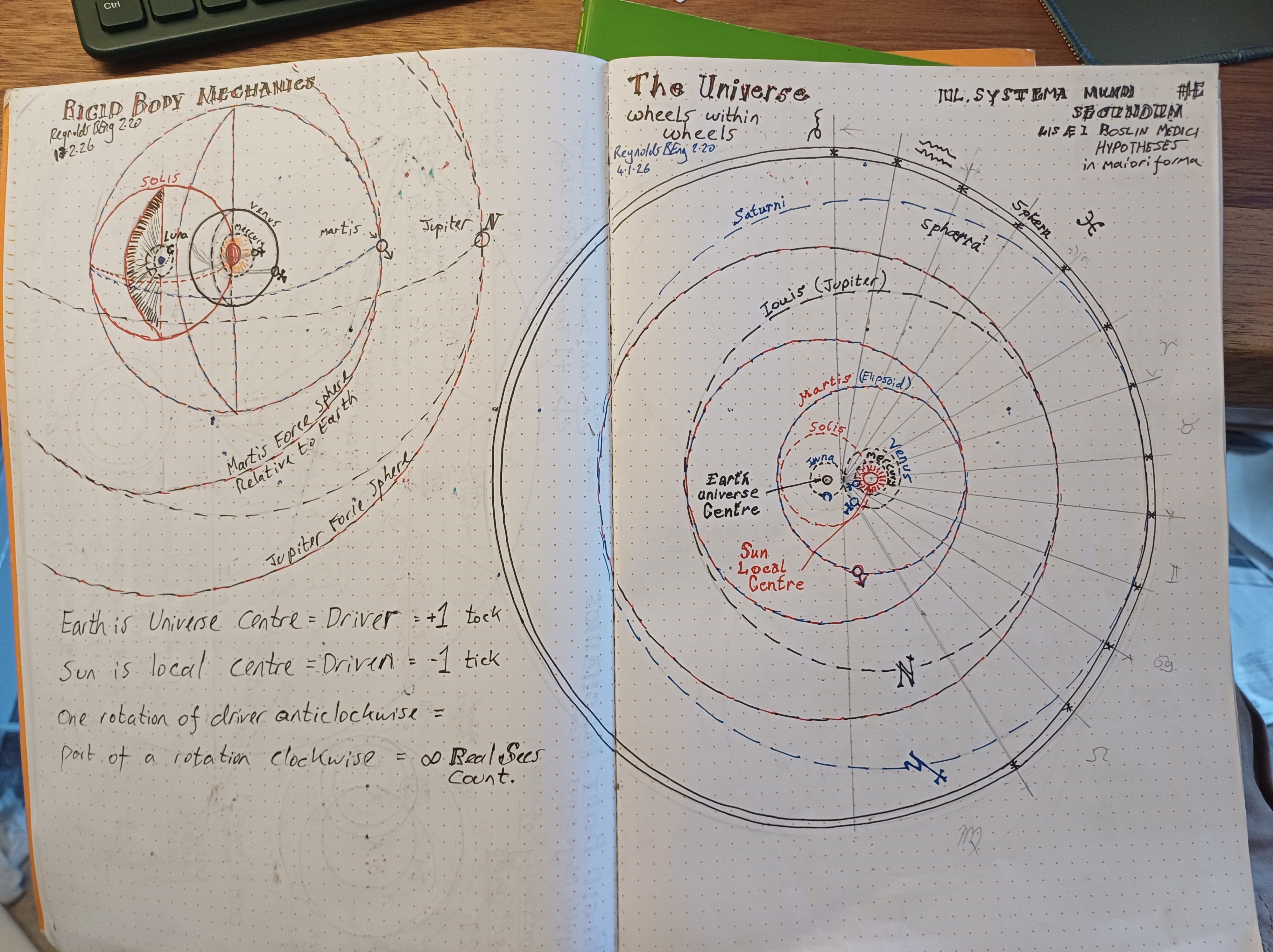
- Earth as preferred cosmic frame
- filament of light / vector potential as Lewe’s meaning
- auxetic infinite energy from water
- double-slit as proof of the tank model
- coded messages placed by Lewe for a future finder
Those claims may be discussed elsewhere. They weaken Project 2 if they are mixed into the hoop-stress derivation.
How to move Project 2 forward from here
Do the next four steps in this order.
Step 1 — Freeze the definitions above.
Do not add new symbols until these are used consistently in the derivation.
Step 2 — Write the free-body of a diametral strip.
Classical part: \(\sigma_\theta t = pr\).
Then state, in one paragraph, the extra circumferential force you assign to judder / closed-ring reassembly, and why it appears as \(+\sigma_R\).
Step 3 — Give \(\sigma_R\) a dimensionally honest expression.
Even a first form is enough, for example in terms of residual second-moment / twist ratio / modal amplitude. If you cannot yet write \(\sigma_R = \ldots\), say so and treat it as a residual to be bounded, not as a finished formula.
Step 4 — Separate “Lewe showed charts” from “Reynolds adds \(\sigma_R\)”.
That single distinction is what makes the paper reviewable.
If you want the next increment immediately, I can draft Section 3 of Project 2 from these definitions: the diametral free-body, the classical term, and the first explicit statement of \(\sigma_R\), with Lewe cited only as historical geometric source.
and following
Section 3 — Derivation of the geometric ring-tension term
3.1 Classical free-body
Consider a thin cylindrical shell of internal radius (r) and wall thickness (t), subjected to internal pressure (p).
Cut the cylinder on a diametral plane. Vertical equilibrium of one half requires that the pressure force on the projected diametral area be resisted by the hoop stress acting on the two cut wall faces:\[ p \cdot 2r = 2\,\sigma_{\theta,\text{classical}}\, t \]
hence\[ \sigma_{\theta,\text{classical}} = \frac{pr}{t} \]
This is the complete membrane result if the wall is treated as a mono-stable continuum whose only circumferential resistance is ordinary hoop stretch.
3.2 What the classical cut omits
The same wall is also a closed ring. Once the circumference is recognised as a closed geometric object, diametral equilibrium may omit a second circumferential action: the force required to keep the ring assembled as a ring while load is carried.
In this paper that omitted action is called geometric ring tension. It is written as a stress \(\sigma_R\) acting in parallel with the classical hoop stress.
3.3 Augmented equilibrium
The working equilibrium statement is therefore\[ \sigma_\theta = \frac{pr}{t} + \sigma_R \]
Limiting check:
- if the extra circumferential restoration is averaged away (mono-stable assumption), \(\sigma_R = 0\) and the classical equation is recovered;
- if the closed-ring restoration is admitted, \(\sigma_R > 0\) and the designer sees an additional circumferential contribution.
This is the claim of Project 2. Lewe 1915 supplies the historical geometric setting in which such a term could remain implicit inside charts. He is not cited as the author of the modern additive equation.
3.4 Identification of \(\sigma_R\)
\(\sigma_R\) is identified with circumferential judder: discrete reassembly of contact around the closed ring as the wall carries hoop load.
Working statement, not yet a finished constitutive law:\[ \sigma_R = \frac{M_R}{Z_R} \]
where
- \(M_R\) is the circumferential restoring action associated with closed-ring reassembly;
- \(Z_R\) is the corresponding geometric section modulus of the ring/disc.
Equivalently, in modal form for later control (Appendix B):\[ \sigma_R = \sigma_R(k,m,S_{m^4}) \]
with radial wave-number\[ k = \frac{j_{\nu,s}}{R} \quad \text{or} \quad k = \frac{j’_{\nu,s}}{R} \]
The existence of \(\sigma_R\) does not depend on Appendix B. Appendix B only treats its spatial control once the term is admitted.
Residual unknowns
These are the quantities that still have to be decided before Project 2 is closed. They are listed so you can think about them one by one.
| Symbol / item | What it stands for | Present status | Decision needed |
|---|---|---|---|
| \(\sigma_R\) | extra circumferential stress | defined as additive term | choose whether it is a stress, a force per unit height, or both, and keep one convention |
| \(M_R\) | restoring action of the closed ring | named, not derived | is it a moment, a couple from second-moment geometry, or a membrane residual? |
| \(Z_R\) | geometric modulus that converts \(M_R\) into stress | unnamed beyond “disc second-moment” | write the actual geometric expression in (r) and (t) |
| \(S_{m^4}\) | residual bending / centroid term from the drawings | used in notes, not yet in the equilibrium equation | either bring it into \(M_R\) explicitly or retire it from Project 2 |
| (h) | moment duration of one judder cycle | modelling interval only | keep as a concept, or give it a numerical bound for tanks |
| (m) | circumferential wave order | Appendix B | state the default design case (\(m=0\) axisymmetric, or \(m=2\) ovalisation) |
| Magnitude of \(\sigma_R\) | the number that would change wall thickness | only the 18–20% indication exists | replace with a first estimate or call it a bound to be measured |
| Sign convention | “positive ring tension” | stated | confirm \(\sigma_R\) is always tensile for internal pressure |
| Independence from (p) | does \(\sigma_R\) scale with (p), or is it a geometric residual that exists even at small (p)? | not decided | this is the most important unknown |
| Test that could falsify \(\sigma_R\) | experiment or numerical check | Project 3 only named | name one observable now: strain gauge hoop excess, ovalisation lock-in, or modal shift |
The two unknowns that actually decide the paper
1. Does \(\sigma_R\) scale with pressure?
If \(\sigma_R \propto p\), then it is only a correction factor and can be absorbed back into a coefficient.
If \(\sigma_R\) has a geometric part that does not vanish as \(p \to 0\), it is a true extra term and the paper has a distinct claim.
2. What is the geometric expression for \(Z_R\)?
Until \(Z_R\) is written in (r) and (t), \(\sigma_R = M_R / Z_R\) is a name, not a derivation.
Everything else (Bessel control, translations, Navier–Stokes appendix) can wait until those two are settled.
If you want the next increment, take unknown 1 first: one paragraph stating whether \(\sigma_R\) is pressure-proportional, geometry-residual, or a sum of both. That single choice determines the rest of Section 3.
29th Aug
I’m adding figures here that I want Grok to think about for Project 3