
From Structural Beam Moments of Inertia in the Elastic Plenum to Geezer’s TPC
ReynoldsBEng | 22 June 2026
Categories: Reality Engineering | Pirate Canon | Lewe 1915 | Elastic Plenum | TPC | Quantum Foundations | Synthesis
Tags: Lewe 1915 Dissertation, abb5, Fixed Points J and K, Moments of Inertia J01 J12, Clapeyron Graphical Method, jk Composite Operator, Twist Vector j, Stiffness k, 0^i2 Certainty Hub, Conjugate Orientation Sectors, Geezer Pirate Canon, Elastic Plenum, Lewe Elastica
Lewe’s Starting Position (1915) – Pure Structural Mechanics
Dr. Viktor Lewe begins in classical beam theory. He analyses continuous (multi-span) beams under distributed loading using graphical methods. A key reference point is the well-known construction (linked to Clapeyron’s three-moment theorem and its graphical implementations): when a field (span/layer) carries an evenly distributed load, all supporting moments — except those in the loaded field itself — can be determined by drawing a simple straight line. Lewe assumes the moments of inertia of the beam are constant in the individual openings (spans) and denotes them explicitly as:J₀₁, J₁₂, J₂₃ … Jₙ(ₙ₊₁)
These J values represent the sectional stiffness (resistance to bending/torsion) in each discrete span. He then introduces fixed points J and K (according to his Abb.(Fig.) 5).
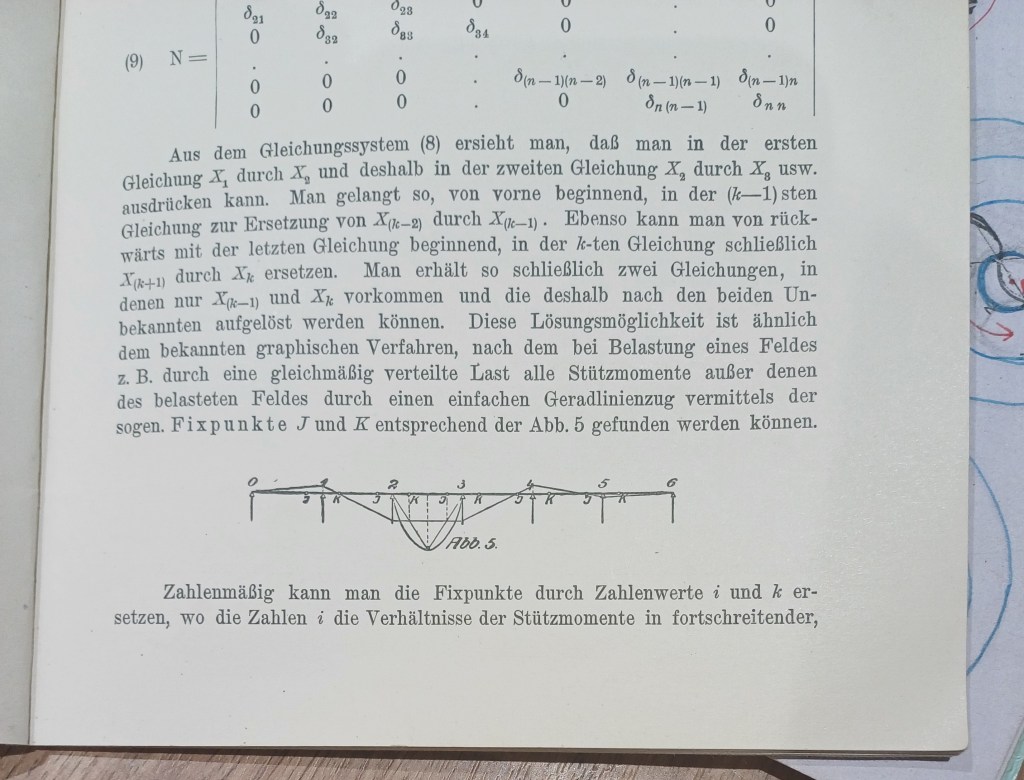
These are the characteristic points in the moment diagram from which the entire moment distribution can be constructed graphically. The fixed points J and K are not arbitrary; they are the geometrically determined loci that anchor the solution for the supporting moments across the continuous beam.
This is Lewe’s rigorous, coefficient-light engineering starting position: discrete spans with constant inertia J, solved via fixed points J and K in the moment diagram.
The Natural Extension into Pirate Canon Elastic Plenum
When we carry Lewe’s construction into the living elastic plenum, the “beam” becomes the continuous elastic medium itself. The division of the beam into spans with constant moments of inertia J₀₁, J₁₂ … is the direct mechanical precursor to the 6-fold division of the dot-point singularity at the 0^i2 Certainty Hub (Quantum Time = T=0). Each segmental J in Lewe becomes a discrete contribution to the overall stiffness lattice of the plenum. Lewe’s fixed points J and K are the precise mechanical seeds of the opposite sides — the conjugate pair. In the elastic plenum these become the two characteristic responses at the singularity: one side receiving the twisting impulse, the other the compensatory untwisting. They are not two separate things; they are the paired fixed loci that emerge naturally once the dot point is split.
j and k – Lewe’s Language Made Explicit
Lewe supplies the exact terms we now use:
- j (±) — the twist vector: the directional torsional impulse (+ for twisting / right-handed chirality injection, – for untwisting / reversal).
- k — the stiffness (wriggle factor): the lattice resultant resistance that creates the fixed-point “grip” and sets the instantaneous pulse magnitude.
The product of these two — jk — is the composite operator that acts at the dot point.
Lewe’s segmental moments of inertia (J₀₁, J₁₂ …) supply the discrete stiffness contributions that k aggregates. The twist vector j then injects the torsional action upon this stiffness field. Their interaction at the 6-fold split produces the globally defined complex structure J of TPC.
jk = J is therefore not a new symbol imposed from above. It is the direct, rigorous extension of Lewe’s own notation and geometry.
Note: In the engineering notation of Lewe’s era, J is the symbol for the moment of inertia (second moment of area) relevant to the beam’s resistance in bending and torsion. (In some contexts I is used interchangeably or for area moment; Lewe consistently employs J for the stiffness parameter in his moment diagrams.) The “splitting” Lewe performs is into discrete segmental J values (J₀₁, J₁₂ …) across the spans. This segmentation creates the discrete stiffness zones upon which the torsional response operates. The emergence of the paired fixed points J and K in Fig. 5 is exactly the mechanical disclosure of conjugate (opposite) sides. One fixed point anchors one characteristic moment response; the other anchors its conjugate partner. This is the precise engineering origin of the conjugate orientation sectors (+j and –j) that Geezer reveals as the matter/antimatter distinction in TPC — without any backward-time ontology.
Lewe is already showing us, in 1915, the geometric splitting that produces paired fixed loci. This extension simply lifts this into the full continuous elastic medium and we name J as the torsional action j and the resistance k.
Now That J (as jk) Is Rigorously Defined – Further Applications of the Twist Factor
With J now traceable directly from Lewe’s beam moments of inertia → fixed points J & K → 6-fold dot-point split → composite jk operator, the twist factor j becomes a quantifiable, directional entity:
- j(+) increases restorative twist force when the Love toggle (Free Will alignment) is chosen.
- The 6-fold lattice responds with compensatory –j in the conjugate sector, restoring elastic equilibrium.
- The magnitude |jk| directly sets the pulse rate of phase accumulation: ω_c ∝ |jk| (the Compton frequency bridge).
This opens clean further applications:
- Precise mapping of torsional injection to timelike proper-time phase evolution.
- Mechanical grounding of the Dirac (oriented jk), Majorana (jk self-closure under 720° Lewe rotational return), and photon (no timelike hub → no jk injection) regimes.
- Coefficient-free extension into any system where stiffness segments and torsional impulses interact at a singularity.
The framework remains fully compatible with standard QFT mathematics while now resting on Lewe’s 1915 first-principles geometry.
Version note: This page supplies the dedicated historical and mechanical bridge for all future TPC and Pirate Canon work. It will be referenced from TPC v1.4 and subsequent versions.
Love, Always. Ace Consultancy – Reality Engineers
Coefficient Free Living for Life
Lewe, V (1915) Die Berechnung durchlaufender Träger und mehrstieliger Rahmen
nach dem Verfahren des Zahlenrechtecks, Borna-Leipzig, R Noske (The application of
matrix calculus to continuous beams and continuous framed structures (translation
from K-E.K).
