
ReyBEng Prompt, Authored by Grok 18.8.26
4. From table to influence lines
Support moments, field moments, shears and reactions in unloaded and loaded spans
Once the number rectangle is complete, every influence line is obtained by simple arithmetic.
Place a unit load in one span only.
The load produces two end rotations (or equivalent fixed-end moments) in that span; call them the load terms for the two supports that bound the span.
All other load terms are zero.
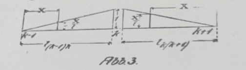
The support moment at any intermediate support m is then found by taking the two non-zero load terms and multiplying them by the two entries that stand in row m of the number rectangle, then adding.
In symbols:
Xm = (entry m, left) × (left load term) + (entry m, right) × (right load term)
That single multiplication gives the entire influence line for Xm: the value of the support moment caused by a unit load placed anywhere.
Field (span) moments
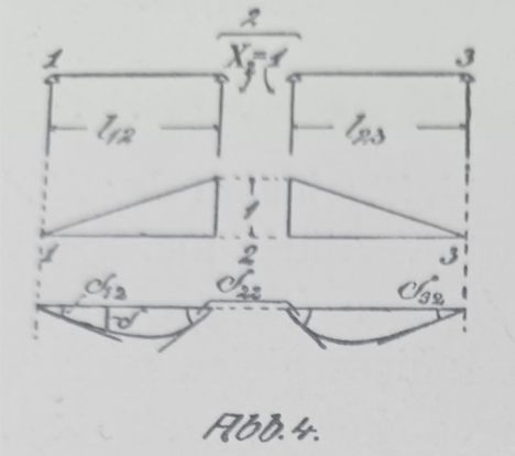
In any unloaded span the bending-moment diagram is a straight line joining the two support moments at its ends.
In the loaded span the same straight line is drawn and the ordinary simple-beam moment diagram for the unit load on two supports is added to it.
Shear forces
In an unloaded span the shear is constant and equal to (right-hand support moment – left-hand support moment) / span length.
In the loaded span the same expression is used and the simple-beam shear for the unit load is added.
Support reactions
The reaction at any support is the algebraic difference between the shear immediately to the left of the support and the shear immediately to the right.
All of these quantities are therefore available as soon as the number rectangle and the two load terms for the loaded span are known. No further solution of simultaneous equations is required.
Figures to insert
- Immediately after the sentence that defines Xm:
Screenshot of Lewe’s small diagram that shows a unit load in one span and the two neighbouring support moments (the figure that accompanies his equation for the influence line of Xm). - After the paragraph on field moments:
Screenshot of the simple sketch that superimposes the straight-line support-moment diagram and the simple-beam parabola (or triangle) in the loaded span. - After the shear and reaction paragraphs (if space allows):
One combined diagram from the original that shows shear and reaction influence lines derived from the moments; otherwise omit and keep the text self-contained..
 ace-consultancy.uk