
ReyBEng prompt, Authored by Grok 18.8.26
3. The number rectangle itself
Flexibility coefficients, continued fractions, fixed-point ratios, and the assembly of the table
Lewe begins with the cut (primary) system: the continuous beam is imagined divided into separate simply-supported spans. The unknown support moments X1, X2,…, Xn are then re-applied as pairs of equal-and-opposite moments at each cut.
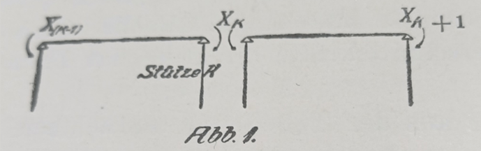
*For any single span of length l and constant flexural rigidity EI, a unit moment applied at the left end produces a rotation at the left end and a smaller rotation at the right end. The same unit moment applied at the right end produces the symmetric pair. These rotations are the flexibility coefficients of the span. Because the spans are independent in the primary system, the only non-zero coefficients that appear in the global equations are those that couple neighbouring supports. The continuity condition at each intermediate support therefore involves at most three consecutive moments, and the whole set of equations has a narrow banded coefficient matrix.
The diagonal entries of that matrix can be evaluated by continued fractions. Starting from the left-hand end one forms the finite continued fraction whose successive terms are the flexibility ratios of the spans; the value of the fraction is the leading coefficient a11. An identical calculation started from the right-hand end yields ann. At every intermediate step of each continued fraction a simple ratio appears; these ratios are exactly the fixed-point ratios already known from graphical statics. Lewe denotes them i (forward direction) and k (backward direction).
Once a11, ann and the complete set of i and k ratios are known, the rectangular array is filled by successive division:
- move leftward from the main diagonal by dividing by the appropriate i;
- move rightward by dividing by the appropriate k.
Symmetry of the flexibility matrix guarantees that the finished rectangle is symmetric about its main diagonal. Every entry amk is now a pure number (or a pure multiple of 1/EI) that multiplies the load terms when the support moments are required.

Lewe begins with the cut (primary) system. The continuous beam is imagined divided into separate simply-supported spans that meet only at the supports. Abb. 2 shows the arrangement: the supports are numbered consecutively 0, 1, 2,…, n, (n+1). The unknown support moments X1, X2, …, Xn are then re-applied as equal-and-opposite pairs at each intermediate support so that the original continuity of the beam is restored. Each span has its own length (l01, l12, l23, …) and its own constant moment of inertia (J01, J12, J23, …). Because the spans are treated as independent in the primary system, the only flexibility coefficients that appear in the global equations are those that couple neighbouring supports. The continuity condition written at each intermediate support therefore involves at most three consecutive moments, and the whole set of equations forms a narrow banded matrix.
The rectangle is therefore not a new physical theory; it is a compact, once-and-for-all evaluation of the minors of the banded continuity matrix. After it has been built, every subsequent numerical question about the beam is reduced to looking up two or three entries and performing a few multiplications.
That is the organisational gain Lewe offered the practising engineer of 1915.
*Footnote
The two end rotations caused by a unit moment on a simply-supported span are classical results of beam theory, obtained by direct integration.
For a span of length l and constant flexural rigidity EI, a unit moment applied at the left end produces the linear moment diagram M(x) = 1 – x/l.
Curvature is therefore M/EI.
Integrating twice and setting deflection to zero at both ends yields the rotations:
- l/(3 EI) at the loaded (near) end and – l/(6 EI) at the far end.
The near-end rotation is exactly twice the far-end rotation; the ratio is conventionally written as a carry-over factor of –1/2.
When the unit moment is applied at the right end the values simply exchange.
The beam is symmetric; there is no preferred left or right side and no “handedness” of strength. The 2 : 1 difference arises only because the applied moment has a longer lever arm relative to the distant support.
These four flexibility coefficients (two for each end) are the elementary building blocks Lewe uses for every span. All subsequent entries in the number rectangle are assembled from them by continued-fraction elimination.
 ace-consultancy.uk